Area-Time Product
Area-Time Product (ATP) is the area of a potential target object multiplied by the time of decay, usually in units of m2-years. Understanding how this parameter affects risk can be subtle. ATP is mentioned in the following excerpt from the US debris mitigation guidelines:
“If drag enhancement devices are to be used to reduce the orbit lifetime, it should be demonstrated that such devices will significantly reduce the area-time product of the system… or will not cause spacecraft or large debris to fragment if a collision occurs”
In determining ATP, the size of the potential impactor is critical. For really small objects, the cross-section area (CSA) of the target is appropriate. When the potential impactor is large, the effective CSA can be much larger than the target object. For example, operating satellites are usually several meters in extent. In addition, most of the area of orbital debris is in 2 m objects. The peak of the probability distribution function for Earth-orbiting objects is greatest at about 2 m in , which are spent rocket stages and defunct satellites. The bulk of the area is in objects about 2.0 m in size while the bulk of mass is about 2.5 m in size.
For assessment of ATP for de-orbit methods, we need to distinguish between two types of collisions. First, high-energy collisions, typically hard-body-to-hard-body, can create many significant large debris objects (>10 cm). Second, low-energy collisions, e.g. thin films or tethers impacting an object, can disable operating satellites but do not create dangerous new debris.
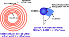
The following figure is a straightforward interpretation of ATP that focuses only on drag CSA. It is this drag ATP that people often consider when determining the ATP relative to impact probability. This is OK as long as the impactor is a small piece of orbital debris. In this figure, we are using a balloon as an example drag enhancement device. The drawing on the left illustrates a bare satellite while on the right an inflated balloon has augmented its CSA.
( » click thumbnail to enlarge « )
Figure 1 Drag Area-Time Product using
a balloon as an example
In both cases, the altitude is lowered by 2 m. However, if the drag area is increased by a factor of 250 by using an inflated balloon, the time to lower the orbit by 2 m is reduced by a factor of 250, assuming the same drag coefficient. In this example, the drag area-time product is the same.
The text of the US guideline seems to be based on an implicit assumption that threat is proportional to this product of area swept out multiplied by how long it takes. So does that mean the collision probability is the same? The answer is no, and we’ll explain below.
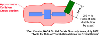
First, we address the implicit assumption that risk is proportional to area. We are all somewhat familiar with the concept of collision cross-section for subatomic particles. They interact over distances much bigger than their physical size. The figure below shows that the center of mass of one object (the debris impactor) can be well outside the projected area of the other object (the target satellite) and still have a violent collision that will generate a lot of new debris.
( » click thumbnail to enlarge « )
Effective collision cross-section area
of an
example satellite configuration
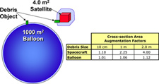
Starting with the projected (drag) area, there is significant augmentation in getting to the collision area when we take into account the dimensions of large debris objects. You see it qualitatively here. But we can see it quantitatively in the next figure where we see the augmentation in area (again using the balloon example) for collisions compared with the original drag area. Even for 10 cm sized debris, the spacecraft area is increased by about 10%, whereas for the large drag device it’s negligible (1%). We are using a balloon as an example because of its simple shape and because the projected area does not change with orientation. For larger debris objects – 2.0 m – the collision cross section area for the spacecraft is 4 times the bare spacecraft area! That’s a very important point. For the balloon, the collision CSA augmentation is only 12%.
( » click thumbnail to enlarge « )
Figure 3 Collision cross-section area
augmentation
by debris impactor size
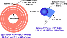
The next figure shows the area-time product using the augmented collision cross-section areas.
( » click thumbnail to enlarge « )
Figure 4 Augmented ATP examples for bare
satellite
and balloon de-orbit device
This is the same situation as before where the orbit lowers by 2 m in both cases. The drag CSA is increased by 250 times and the time to decay 2 m is reduced by the same 250 times. But this time we use the collision cross-section area. We see that the volume swept out is more than 4 times greater for the bare spacecraft than with the large drag device. This already shows that the probability of a collision is reduced when using a large drag device. However, this does not yet get at the danger associated with the collisions. We’ll look at that next.
Pretty much any collision between hard bodies will completely obliterate both objects and create two new clouds with MANY large fragments (>10 cm). We saw that with the Chinese ASAT demonstration in 2007. But a collision with an extended thin film a few microns thick is a lot different. The film will be vaporized, but the momentum transferred into the colliding hard body is quite low on a per area basis. It’s a relatively low energy collision. It may bend back a solar array boom. It may even break off a solar array. But it does not cause significant fragmentation. The danger is a lot less. The consequences of a collision are a lot less.
With a large gossamer drag device, only collisions with the central hard body lead to significant new fragmentation. So let’s look at the Debris-generating ATP using the same example balloon device. This is the high-energy collision portion of the area that is shown in red in the next figure. The (augmented) hard body area is the same in both cases. But with the large drag device, the time is reduced by 250x. This means that the likelihood of a collision that will produce lots of dangerous new debris is reduced by a factor of 250.
And you are accumulating that threat at exactly the same rate, minute by minute, as without, but once you get out of orbit, you are done, whereas the bare spacecraft keeps accumulating the threat at that rate for centuries.
In fact, if you deploy the drag device at solar max, the atmospheric density is a factor of three higher than the average density over the whole solar cycle. So actually, there is lower risk of creating new debris (on a minute-by-minute basis) with the large drag device than for the bare spacecraft. But you get the defunct object out of orbit in year versus a few centuries.
The integrated risk of creating new large debris is a factor of 700 or so lower with the large drag device operated at solar max as compared with the bare spacecraft.
Also, if the original spacecraft is operating in the same orbital band as other spacecraft, it will essentially remain in that same band for a long, long time. With the balloon de-orbit device, you get it out of that band quickly.
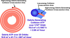
( » click thumbnail to enlarge « )
Figure 5 Debris-generating ATP examples for
bare satellite and balloon de-orbit device
In this next discussion, we are going to calculate the Area-Time-Product of several different de-orbit system concepts shown in the next figure. First, it is important to emphasize that the effective collision cross-section Area-Time-Product (ATP) is a function of the size of the impacting object of interest. For this calculation the impactor size of interest is the peak of size distribution by area of orbital debris or 2.0 m. This is also a conservative characteristic size for typical operating satellites.
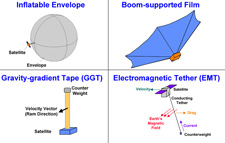
( » click thumbnail to enlarge « )
Figure 6 Some example de-orbit system concepts
The size of all of the different de-orbit concepts is normalized in order to achieve decay in about one year near Solar Max, although Solar Max would only affect atmospheric drag devices. The example bare reference satellite to be de-orbited is at 830 km altitude and has a configuration similar to that shown in Figure 2 (a 1 m cubic bus with two 2 m by 0.75 m solar arrays) with an drag cross-section area of approximately 4 m2.
In the next figure we compare the bare satellite with a few different de-orbit systems each attached to an identical hypothetical bare satellite. The three drag devices are all assumed to use a very thin film of a few microns and to have the same projected area of 1000 m2. This is sized to bring down the spacecraft in one year when operated at Solar Max to get all the help we can from the atmosphere. The rigidizable space inflatable de-orbit device, not shown, would be the same size as the inflation-maintained, ultra-thin balloon device.
The electromagnetic tether size is an estimate based on scaling from the available literature. We have not analyzed EMTs to the same level as we have with atmospheric drag devices, but we believe this size is representative. One caveat is that EMT devices have their best performance when the magnetic field lines run normal or 90° to the tether. This means an EMT will have its best performance in near equatorial orbits and its worst performance in polar orbits. That’s a pity because one of the most dangerous orbital regions is near polar orbit between 750 and 900 km altitude, where a Russian satellite struck an Iridium satellite.
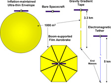
( » click thumbnail to enlarge « )
Figure 7 Size of example configuration several de-orbit devices for a one
year decay at Solar Max of a reference satellite
In the next figure, the hard body elements are shown augmented (red shading) based on potential collisions with large debris objects. This shading highlights the high-energy collision portion of the area that can result in more 10 cm-sized debris.
For booms that support an ultra-thin film the average density is sufficient to cause significant fragmentation of the large impactor debris object generating significant 10 cm objects.
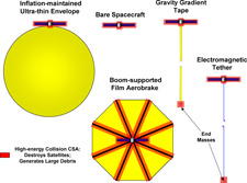
( » click thumbnail to enlarge « )
Figure 8 Augmented area of de-orbit devices that
can cause
debris-generating collisions
In the next figure, we highlight, in green shading, the low-energy collision portion of the area that can cause satellite-disabling collisions, but which cannot generate new orbital debris.
Here we’ve assumed a very lightweight tether of perhaps 3 g/m. But if the tether were substantial, then its collision cross section area could be red shaded, too. That would then pose a much more severe hazard.

( » click thumbnail to enlarge « )
Figure 9 Augmented area of de-orbit devices that
can cause satellite-disabling collisions
The following table compares the augmented area time products for the high-energy and low-energy portions for each of the de-orbit system concepts studied. The N/A (not applicable) in the chart below under low-energy collisions for the bare spacecraft and rigidizable space inflatable is because all collisions are high-energy.
Table 1 Effective Area-Time Product for example de-orbit methods

Note the reference bare satellite ATP for high-energy collisions is very large. The value for low-energy collisions is not applicable (N/A) because there are NO low-energy collisions with the bare satellite. They all cause dangerous new orbital debris. Immediate and controlled de-orbit by means of on-board propulsion is the lowest ATP - almost zero. EMTs and GGTs both have very high ATP for low-energy collisions that can disable operating satellites. Their ATP is almost 10-times higher than the bare satellite. This calculation underscores why tethers are really too dangerous for operation in LEO. Both the inflation-maintained ultra-thin envelope and boom-supported film concepts have low-energy ATPs about an order of magnitude lower than the bare satellite. The rigidized space inflatable has the second worst ATP for high-energy collisions behind the bare satellite.
Some proponents of these methods propose longer decay periods (e.g. 25 years), but that makes them a higher threat by a factor of at least three since they are not operated near Solar Max and thus do not take advantage of the higher density atmosphere.
|

